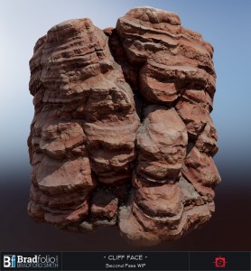
Substance: Red Rock Cliff Face
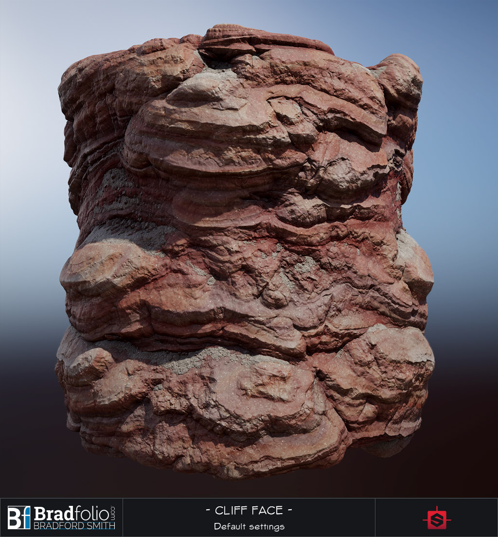
Making Polycount’s Weekly Substance #8: Red Rock Cliff Face
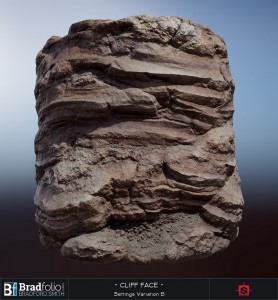
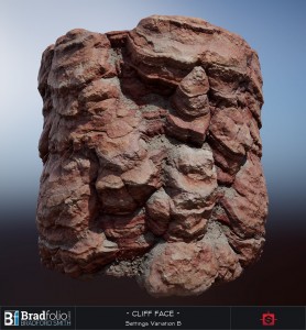
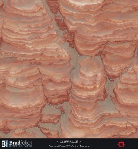
100% Naturally organic Substance Designer goodness! This red rock cliff face has the following tweakability:
- Primary shape scale and distribution
- Editable layers of detail
- Rock layering / erosion effects
- Sand and stones that accumulate on the tops of the rock face
Rendered with Marmoset Toolbag 2
Process and Breakdown
Philosophy:
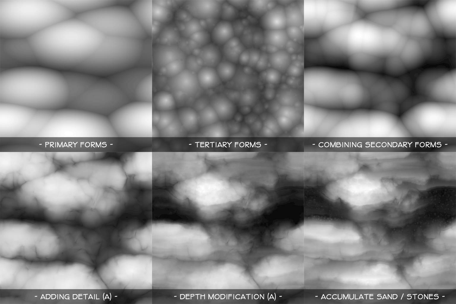
I almost always approach my Substance Designer workflow like I would a sculpture. I start with very simple, abstract primary and secondary forms. While these forms are very deliberate, they usually aren’t much to look at when looked at in isolation. But when these layers are combined in interesting ways, together they produce something much more complex and believable. Some layers are additively combined to build up the forms and layers of detail, and some layers are subtracted in order to create new and interesting forms.
You can see in the image below how the main forms are broken down and accumulated. The isolated form layers themselves are actually VERY simple. They are merely a suggestion of particular frequency of detail.
Additive and Subtractive Approaches:
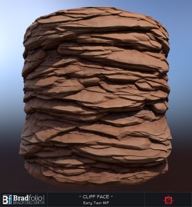
You can see from these WIP images below, how my exploration of form began.
The first pass was an additive approach created by instancing rock layer shapes. This gave me the layered I was after, however I found it hard to influence the layers by larger low frequency shapes.
As an alternative to my first pass, I tried additively combining different Parabaloid Scatters and noises in order to build up the low frequency rock face that I had imagined. This gave me all the rock surface qualities and details that I wanted, but did not include the eroded layered forms.
Toward the end of the height map creation I subtracted the eroded rock layer, which ended up yielding even more interesting, varied, and complex forms than the strictly additive workflow.
Cutting Away the Layers:
Cutting away the layers was actually quite simple. For this I imagined a bunch of angled razor blades cutting through the texture plane. I ended up using multiple blend methods and custom FX-Map to really drive the effect home, but the core of the look is created by Directionally Warping a Splattered Linear Gradient.
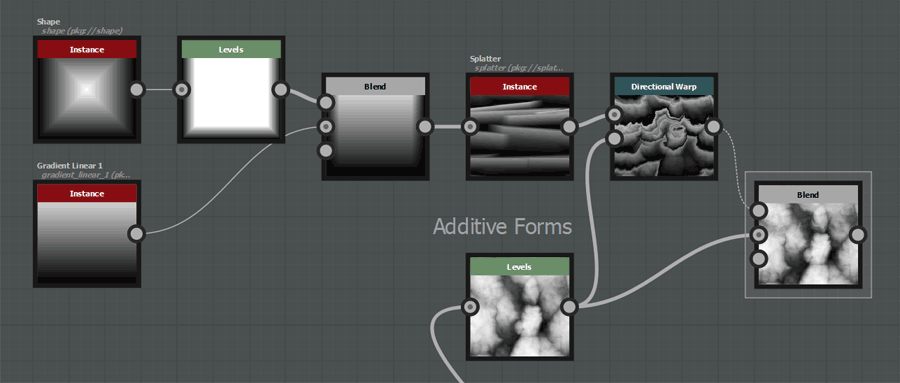
Using a splatter node to instance linear gradients that get warped and subtracted from the main rock forms
Conclusion:
By crafting simple height maps that represent various frequencies of forms in isolation, I gain full control over the editing, adding, and replacing of multiple frequencies of detail. This opens up my workflow to the possibility of “happy accidents” through experimentation. If I wanted I could completely change the underlying rock forms, and get a completely new layered rock look. Or simply remove the subtracted layer effect, and have a nice rock height map.
See more on Polycount’s Substance Designer Challenge Thread:


You can get a subdivision relative to the mask on Toolbag?
I don’t think there is anything dynamic about the Sub-Division in Toolbag. I usually just increase my Sub-Division Tessellation amount until it diminishes returns, and then I eyeball my Displacement Scale. The Displacement scale can also be relative to the object’s bounding box, or be expressed in scene units.
Awesome brad Ill be referring to your stuff for info soon.
Thanks Eric. I’ve got more info in the works for sure!
This is incredible work Brad. Really creative use of gradients sculpting into rock. Are you on Polycount? I’d like to follow your work!
Thank you Mark! I sure am on Polycount. You’ll find links to my WIP threads at the bottom of this post, or you can head over to my profile by following this link: Polycount Profile: Bradford Smith
wow! are you planning to share the template?
At the moment it’s hard to share the .sbs file since it references many custom substances from a large personal library. I do however have a lot of content planned for the coming months, including some downloads and tutorials. Stay tuned for more!
this could mean a lot for the substance community – i am very excited
Hey! Super inspirational to see you’re different substances! I’ve just started working with this beautiful tool and I set out to reverse engineer you’re base shapes based on your first gif.
Combing the tertiary forms are beyond me though. I want to think that you’re directionally wrapping your base shapes with the inverted tertiary form. But I see so many directions and details going on. With the main shapes staying pretty much in place. Wrapping in a bunch of directions and combing dosen’t give me the same result/just ads tertiary sized noise all over. I really love the chunkiness! Would you give me a clue to whats going on?
Cheers!
Hi Valdemar, those are good observations. I am indeed directionally warping each layer by the other, and multiple times, in multiple directions. Conceptually this is simple, but it will take a bit of function work to get working. This is definitely something you want to make an encapsulated node for.
In short, I warp each layer 1-4 times, after each warp, I then offset the result in the opposite direction by half that amount using a transform node. This keeps the warped layer “in place”. Once layer A is warped, I can optionally repeat the same process on layer B and use the warped layer A as the directional warp mask. This type of setup has led to some very interesting shape combinations for me, and I use it a lot!
Hope that helps, and good luck in the Substance endeavours!
Thank you so much for that! When you’re saying that you offset the result back with a transform, are you doing that manually for every wrap? Cause I tried to set a second dir warp to move it back to position, using a solid color as the strength mask, but I never got a good result. I ended up warping in opposite direction with the same mask instead. I wish the result would be a little less generic, but it works better then a single warp at least.
I don’t have to do it manually because I’ve saved a custom warp node to my library with all those controls built in. Your method of using a second directional warp with the opposite angle and half the intensity SHOULD work (have a look at the linked image below).
In my case I actually use a Transform2D node. You’ll notice that a warp intensity value of 256 is equal to an offset of 1. So you do a simple function in your Transform2D to control the offset amount by the warp intensity value. The other advantage to using a Transform2D node is that you can offset with the Nearest filtering method to avoid any more Bilinear filtering height degradation
Thanks for the explanation! I don’t know why I didn’t succeed the first time trying to recreate it, but I went back and set it up exactly like you are showing above.. I’ll definitely try to get the transform2D way to work to!
Thanks again!
Glad it worked!
Thanks for breakdown. Very inspiring!
Thank you! I’m glad you enjoyed it